

Many loaders have a self-leveling valve for the boom lift and bucket tilt hydraulic circuits. The basic concept is that when you raise the main boom, the bucket is tilted down to keep it level with the ground rather than locked to the main boom. This is particularly handy when you need the load to remain level such as when using pallet forks, but it is also nice with a bucket of material so it doesn’t spill over the back of the bucket when raising the boom.
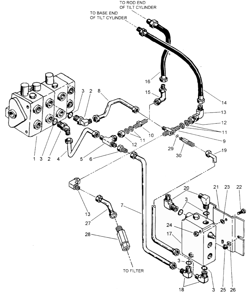
I bought a Mustang skid steer that had a problem: the bucket would leak down. I isolated the problem to being inside the self-leveling valve. This magical block of steel had 4 hydraulic lines connected to it and ports all around the sides. In order to determine why it was leaking, I first had to figure out how it worked. The diagram below shows how the valve connects to the bucket tilt cylinders. The self-leveling valve is in the bottom right corner.
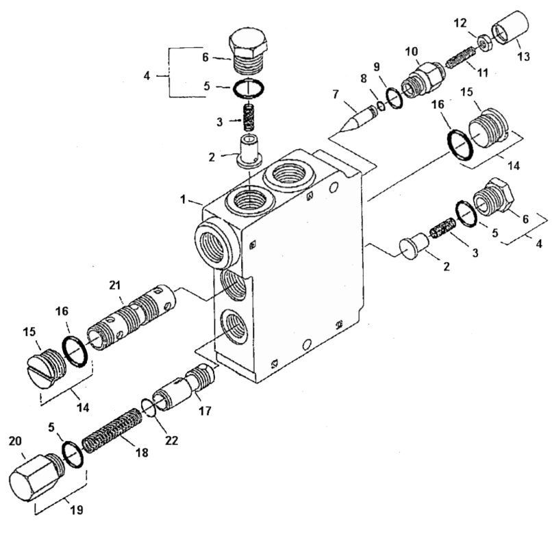
This picture shows what parts go inside the valve.
The next picture is an internal schematic of what is going on in this valve block. The two ports on the top (A and B) are plumbed in series with the main boom lift cylinders. Notice that directly between these two ports is a check valve (#16) being held down by a spring (#18). When you lower the main boom, oil flows through the check valve from A to B, bypassing the rest of the circuit. When you raise the main boom, the check valve is closed and oil has to flow from B to A through the other parts of the circuit.
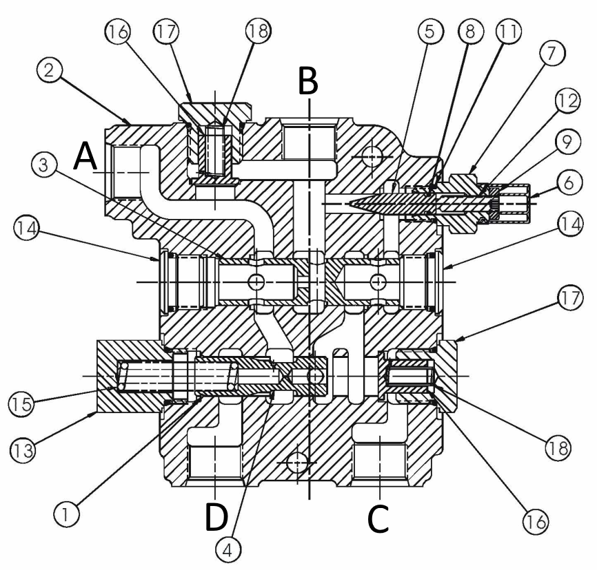
The two ports on the bottom (C and D) are plumbed in parallel with the bucket tilt cylinders. There is another check valve (#16) on port C, and a spring loaded spool (#4) to block the flow on port D. More about this spool in a bit.
In the middle of the valve is a flow divider. As oil comes in port B, some oil goes through a needle valve on the right (#5) and some goes to the center land on the flow divider spool (#3). The oil going into the flow divider spool can only go to the left towards the A port. The oil that goes through the needle valve will continue on to the C port. The pressure on each of these paths push on opposite sides of the flow divider spool. As the spool moves from one side to the other, an orifice on one side gets larger and an orifice on the other side gets smaller. This change in flow keeps the pressure balanced on each side of the spool. This is how some percent of the oil can be sent to the C port while the rest goes to the A port. The proportion is determined by the needle valve.
Oil going to the C port then normally pushes open the check valve above port C. This oil tries to push the bucket down. As the pressure increases, it also puts pressure on the right side of the bucket lift relief spool (#4) which is pushed to the right by a spring. As the pressure overcomes the spring, oil is allowed to flow in port D and out port A. As oil drains from the lift side of the bucket tilt cylinders through port D, the pressure on port C will drop, causing the spool to slide right and stop oil flowing in port D.
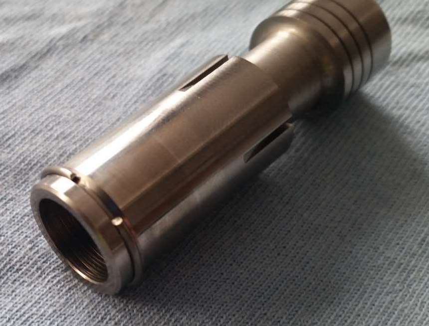
In my case, the problem was a missing retaining ring (#1) on the left side of the spool (#4). That spool was sliding farther to the right than it should have, which allowed oil to move from D to C, causing the bucket to settle down. This picture shows the spool with the new retaining ring installed.
More detailed information about self-leveling valves can be found in patent # US4709618
Last updated: February 29, 2016