

Summary: Allow wireless access to the up/down/stop controls on an industrial overhead door. This is nothing more than a garage door opener for a big door.
Estimated Price: About $150, plus a couple hours to wire up the electronic components
Details: An industrial overhead door has a 3 button control for up, down, and stop. I can use 3 relays to electrically control this door system and simulate a person pressing the buttons. For the control unit, I used a product designed for use in a car as an aftermarket keyless entry system. The product I choose is made by Directed Electronics Inc (DEI). I used model number 450R for the control unit, plus I got a couple of the key fobs that you would carry on your key chain. You can source this part from your local automotive remote start installer, or look for it online.
Since the DEI 450R is designed for use in a car, it requires a 12 volt DC power supply. You can find 12v DC power supply pretty easily at any electronics hobby shop, and you probably have one laying around at home from some device you bought and no longer use. You’ll need a power supply capable of at least 500 mA (half an Amp), but more won’t hurt anything. All it needs to do is have enough power to run the relays.
Also, since the DEI 450R is designed for use in a car for unlocking doors, it is designed to be powered on all the time, even when the car is off. However, it has one wire that goes to the ignition circuit, which is used to put it into programming mode. The instructions on your device may be different, but basically you would turn the car ignition on and off 5 times to put it into programming mode. Since you’ll need to simulate this, just put a switch in between this wire and the +12vDC rail. You can turn that switch on and off 5 times to get into programming mode.
The DEI 450R has 6 outputs, each programmable to a certain key on the remotes. Since I only need 3 outputs, I just ignore the other 3. You could use them to control a second door if you want to. The device grounds the output when it is on. So I wire one side of each relay to an output wire, and the other side direct to the positive 12vDC rail.
Programming mode on the DEI 450R is used to add new remotes to its list. It can remember up to 4 of them. You can also assign which key(s) on the remote control which outputs. I used the door unlock button to open the door, the door lock button to close the door, and the red alarm button to stop the door.

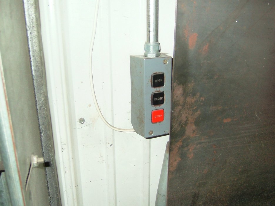

The second image is a button control that is normally used to open/close/stop one of these doors. You just need to hook up relays to do the same thing as pressing a button would. Note that these have an interlock on the stop button, which means that button is normally closed, and when you press it, it opens the circuit. The up and down buttons are normally open, and when you press them, they close, which tells the opener to do that function. To wire a relay on these, the relay will go in parallel for the up and down buttons. For the stop button, you need to use the normally closed contact on the relay, and put the relay in series to the stop button. This way, when you trip the relay, it will open the circuit, just like the stop button would. The interlock is in place so that if the door is moving and the wire gets cut, it will stop moving.
The third image shows the 3 relays, a screw terminal block, the DEI 450R, a box for the programming button and ignition switch, and a 12v DC power supply. This is all mounted to a 1x6 piece of wood, bolted to the side of the building.
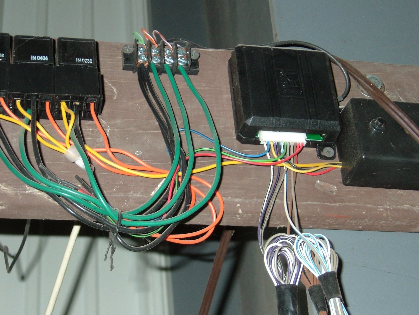
The fourth image is a closer view, showing the wires out of the DEI 450R. Note how I tied off the 3 unused outputs. Also note how the yellow wire on the relays are the (+) input, and they go to the power supply. The orange wires are the (-) input, and they each go to one of the DEI 450R outputs. The relay black wire is the center contact, which all go to a common screw terminal. The green wires are the switched side. Two of the three will go to the normally open (NO) side of the relay, and the other one will go to the normally closed (NC) side of the relay, which is the one used in series with the stop button.
Last updated: November 19, 2009